Connections / Design study / CABLE-RETENTION-R2
Keep the collar captured.
A seated retaining ring closes a nominal retention gap in the original connector.
Retained development study. Dimensions, names and checks belong to this revision—not automatically to the retrofit-only product. Manufactured tank shells are deferred. No installation instruction, certification or manufacturing release is represented.
The source reasoning
Why this detail was investigated.
The collar needs an explicit mechanical stop. R2 adds a groove and collar relief without treating geometric restraint as a pull-load rating.
Read the research and limits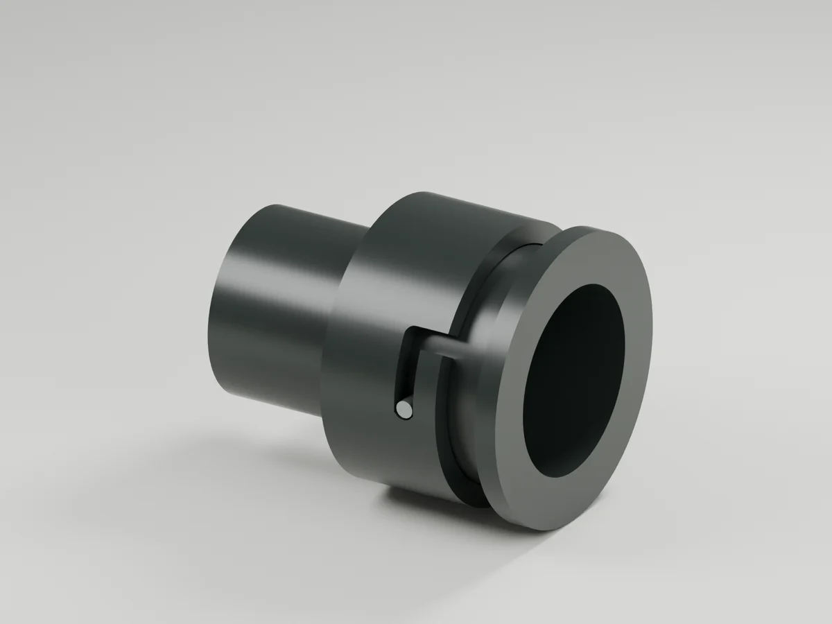
Research record
The detail behind
the study.
Source-linked work for this revision. Reported checks describe the stated model or test; physical qualification and applicability to the current retrofit remain separate.
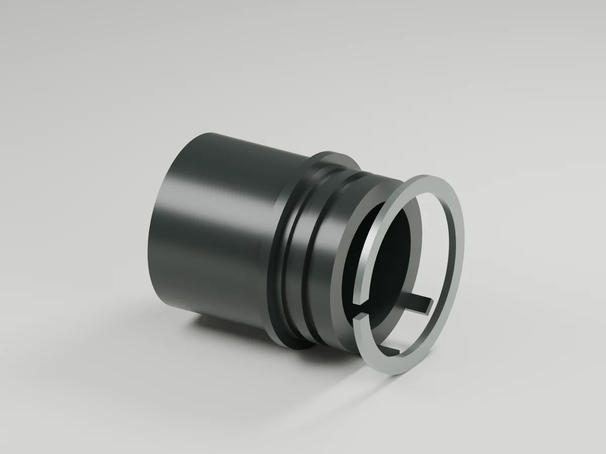
The R1 retaining ring touched a cylindrical body without an axial seating groove. R2 introduces a groove, a seated custom C-ring and controlled collar-flange relief. This closes a nominal geometric retention gap in the connector. It does not establish a pull-load rating.
Geometry now supplied
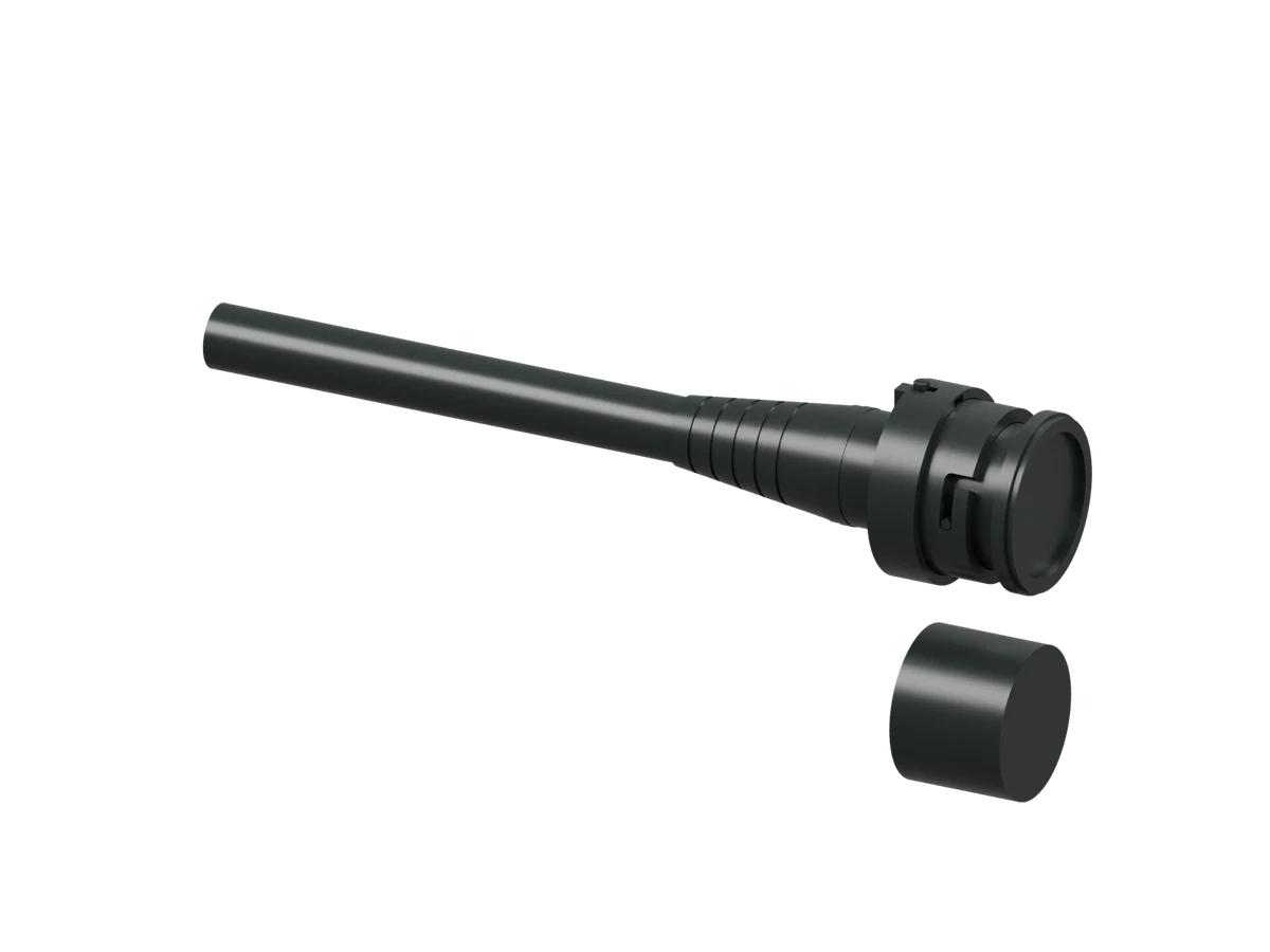
complete-termination.step : complete 457-solid cable and connector with the revised retention parts integrated.
retention-assembly.step : eight-body mechanical subset for inspecting the retention and bayonet interface.
inspection.blend and ring-access.blend : native CAD-derived render scenes. The second view displaces the retaining ring 16 mm axially for visibility; this is an explanatory pose, not a demonstrated installation motion.
Nominal development dimensions
| Feature | Study geometry | Purpose |
|---|---|---|
| Retaining groove | Root diameter 30.4 mm; axial span 15.8–17.7 mm | Axially seats the C-ring |
| C-ring | ID 30.4 mm, OD 36.4 mm; 1.5 mm axial thickness | Captures the collar flange |
| Groove / ring axial difference | 0.4 mm total | Allows nominal ring axial freedom |
| Collar inner capture face | Z14.15–15.85 mm | Clears the body shoulder and nominal ring position |
| Collar front inner relief | Up to radius 18.4 mm | Provides 0.2 mm radial clearance to the ring OD |
| Assembly passages | 3.4 mm tangential width at master/class keys | Lets the collar pass the front keys before ring installation |
All coordinates use the cable's original local Z axis, not the rotated presentation view. These are nominal CAD dimensions, not toleranced released drawings. The centered-ring pose has 0.15 mm nominal collar clearance on each side; ring freedom changes that clearance. The supplemental restraint check moves the ring to its forward groove limit and still finds collar restraint at +0.5 mm displacement. No load capacity follows from interference volume.
Verification
The generation records 172 passing checks, including separate-body validity, nominal interference, positive axial interference at the collar stops, sampled collar installation, sampled 30-degree bayonet rotation and axial approach, and both STEP round trips. Two focused pytest tests pass. Copied-source regeneration matches all 465 STEP solids across the subset and integrated exports by individual Boolean symmetric difference. Both native renders were reopened and their mesh vertices checked within 0.001 mm; the images were visually reviewed. The supplementary floating-ring check passes. The complete R2 repository regression passed:346 tests in1955.40 seconds, terminal exit0. It predates later revision tests.
The motion samples establish nominal configurations, not a continuous swept-volume or tolerance proof. Wrong-class keys, cable conductors and contact allocations retain the R1 study basis.
Required engineering still open
The ring is a custom geometric envelope. Select material/process or replace it with a verified supplier part, then design installation tooling, installation deflection, fatigue and axial capacity. The collar installation path is modeled with the ring absent; the ring's actual expansion and tool access are not yet qualified. The bayonet needs deliberate detent/preload and verified stud attachment. Seal compression, contact spring/termination design, jacket anchorage, complete tolerance stacks and environmental/electrical tests remain open. No energized wet mating, immersion rating or manufacturing release is established by this revision.
Complete connector + cable STEP · Retention subset STEP
Source and revision record
Source: cable-retention-r2/index.html
Source SHA-256: 63be925a1e200a66c2188ffe8bef5e7abfb9ca9ab9ee430e11e7135cdb2eead9
Geometry and images describe this development revision. Current product ratings and manufacturing release require separate qualification.
Keep exploring the research.
Engineering records / Engineering record
Cable Ring Installation Audit
Geometry, analysis and remaining engineering work for Cable Ring Installation Audit.
Engineering records / Engineering record
Cable Seal Audit
Geometry, analysis and remaining engineering work for Cable Seal Audit.
Connections / Development CAD
Link threaded stops
Inspect the latest complete termination geometry with modeled threaded stops.
Return to the current product.
Explore the retrofit-only platform and its compatibility, installation and service objectives.
Explore the retrofit