Engineering records / Engineering record / POST-STABILITY-R1
Post Stability R1.
Geometry, analysis and remaining engineering work for Post Stability R1.
Retained development study. Dimensions, names and checks belong to this revision—not automatically to the retrofit-only product. Manufactured tank shells are deferred. No installation instruction, certification or manufacturing release is represented.
The source reasoning
Why this detail was investigated.
Disposition: retain the 3 mm post walls while developing positive lateral restraint and joints. No post capacity is released.
Read the research and limitsResearch record
The detail behind
the study.
Source-linked work for this revision. Reported checks describe the stated model or test; physical qualification and applicability to the current retrofit remain separate.
Disposition: retain the 3 mm post walls while developing positive lateral restraint and joints. No post capacity is released.
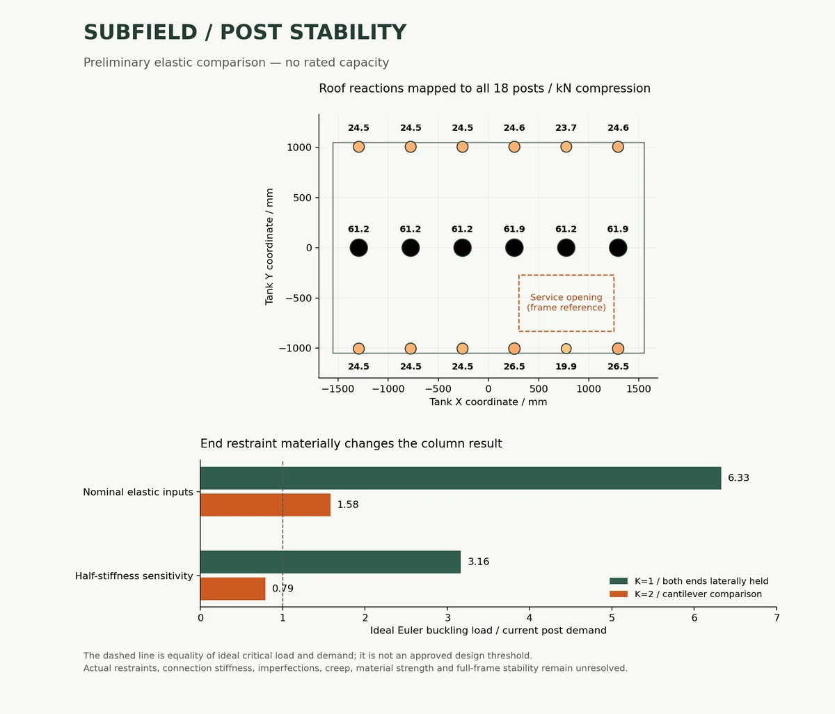
The current CAD contains eighteen 80 x 80 x 3 mm posts, each 1347 mm long. This calculation maps each post by its measured XY position to the latest laminate-based roof reaction.
| Case | Peak load (kN) | Average compression (MPa) | Ideal plate ratio | Euler K=1 ratio | Euler K=2 ratio |
|---|---|---|---|---|---|
| axial-caps_axial_biased-webs_stiffness-1.0 | 60.88 | 65.88 | 4.33 | 6.43 | 1.61 |
| axial-caps_shear_biased-webs_stiffness-1.0 | 61.90 | 66.99 | 4.26 | 6.33 | 1.58 |
| axial-caps_axial_biased-webs_stiffness-0.5 | 60.88 | 65.88 | 2.16 | 3.22 | 0.80 |
| axial-caps_shear_biased-webs_stiffness-0.5 | 61.90 | 66.99 | 2.13 | 3.16 | 0.79 |
Ratios are ideal critical loads divided by current unfactored loads. They are not safety factors.
K=1 assumes both ends are laterally held. K=2 illustrates a cantilever-like condition. Actual post/rail/base joint stiffness and frame sway restraint have not been established. A contact face alone does not justify either condition. A ratio below 1 means the current demand exceeds that particular ideal critical-load calculation. A ratio above 1 does not establish adequacy.
Do not thin the posts. Establish positive lateral restraint and connection stiffness before choosing an effective length or claiming a capacity margin. The next geometry revision must provide a continuous lateral load path from the post through its joints into restrained structure. Adding a collar without analyzing the surrounding frame would not establish that path.
- Load ratios are ideal elastic critical-load / current unfactored demand, not safety factors or approved margins. - Euler K=1 assumes both ends held against lateral translation, with free rotation. K=2 is a cantilever comparison only. Neither is established by nominal CAD face contact. - No proof of actual frame sway restraint, end stiffness, bond strength, connection eccentricity or rotational restraint is included. - Local plate model uses a perfect flat symmetric laminate, simple support along all four edges and uniform axial compression. D16 and D26 coupling terms are retained. - The assumed 80 mm face width is compared with the 74 mm clear width; these are not calibrated corner conditions. - The Ritz result is a finite-basis upper estimate of the ideal elastic buckling load. Refinement is checked, but it is not a measured lower bound. - Material moduli, environmental factors and ply thickness remain preliminary assumptions from the laminate study. - Imperfections, creep, strength failure, damage, local/global interaction, shear deformation, lateral soil/water loading and full-frame instability remain outside this calculation. - Roof reactions are from the fitted linear model with axial post springs; rail, base, floor, bedding and joint compliance remain omitted.
- plate_reference - anisotropic_energy_reference - laminate_reference
The full CAD test suite completed with 58 tests passing in 25.32 seconds. The added buckling checks cover isotropic plates at three aspect ratios, an orthotropic closed-form solution, independent Gaussian energy integration including D16/D26 coupling, Ritz refinement, Euler scaling and invalid inputs.
All eight integrated numerical checks passed. The generator verified the geometry of all eighteen current post solids, mapped their coordinates to roof reactions, and checked the input roof report against its recorded source hashes.
No CAD wall thickness was changed. No physical strength, creep, bond, frame stability or manufacturing qualification test was performed.
The plotted load map uses the nominal axial-cap/shear-web roof case. It is a top-view engineering diagram, not a new tank model.
To reproduce, extract current-cad-source.zip into this folder. From the extracted cad folder:
If the laminate/roof source changes, regenerate laminate_roof.py output first. The post calculation intentionally rejects stale source hashes.
Source and revision record
Source: post-stability-r1/ENGINEERING-REVIEW.md
Source SHA-256: 85078936a9af9aaa2ee3e35b771da84e5063f234e21ea111f2ae6272bdc0902d
Geometry and images describe this development revision. Current product ratings and manufacturing release require separate qualification.
Return to the current product.
Explore the retrofit-only platform and its compatibility, installation and service objectives.
Explore the retrofit