Engineering records / Engineering record / ROOF-DECK-R1
Roof Deck R1.
Geometry, analysis and remaining engineering work for Roof Deck R1.
Retained development study. Dimensions, names and checks belong to this revision—not automatically to the retrofit-only product. Manufactured tank shells are deferred. No installation instruction, certification or manufacturing release is represented.
The source reasoning
Why this detail was investigated.
Status: preliminary engineering geometry. This package is not a manufacturing release.
Read the research and limits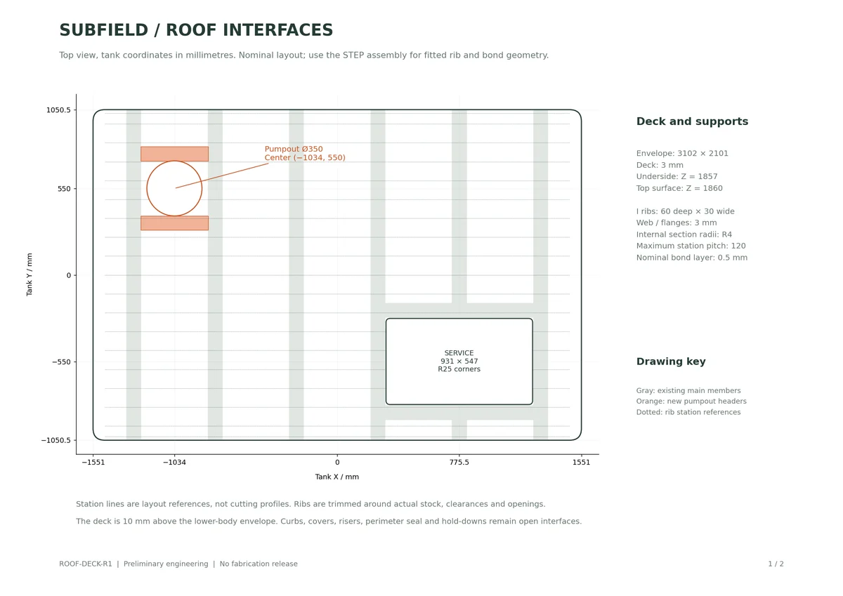
Research record
The detail behind
the study.
Source-linked work for this revision. Reported checks describe the stated model or test; physical qualification and applicability to the current retrofit remain separate.
Subfield ribbed roof development package
Status: preliminary engineering geometry. This package is not a manufacturing release.
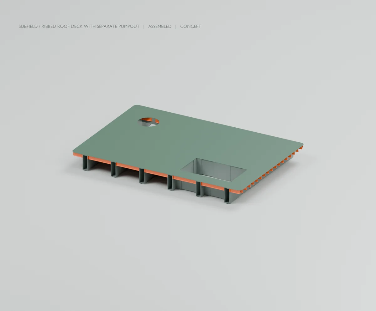
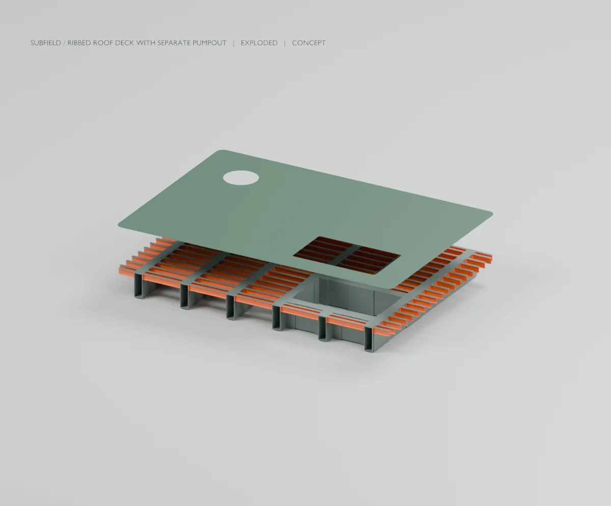
This revision adds the previously missing roof skin, local I-section ribs, fitted bearing strips and explicit bond volumes. It retains the large service opening and adds a separate pumpout bore between two existing main roof members. The earlier formed-wall vessel remains the lower-body geometry. The entire tank is still incomplete.
- Roof skin: 3102 × 2101 mm bounding plan, 75 mm outside corner radius and 3 mm nominal thickness. Underside Z = 1857; top Z = 1860. This is 10 mm above the lower-body study envelope. - Large service opening: 931 × 547 mm, R25 corners, centered at X = 775.5, Y = -550 mm. The current screen/carrier extraction envelopes are checked against the new parts. - Separate pumpout bore: Ø350 mm at X = -1034, Y = 550 mm. It sits in the opposite end bay without cutting another main transverse member. This is a provisional no-entry pumpout interface. - Two new 90 × 100 × 3 mm hollow pumpout headers at Y = 330 and 770 mm, with separate 4 mm end plates and 0.5 mm bond volumes. - 121 fitted I-rib solids, nominal section 60 mm deep × 30 mm flange width, 3 mm web/flanges and R4 internal roots. Nineteen Y stations include dedicated edge rows; maximum station pitch is 120 mm. - Enlarged nominal 60 mm wide × 6 mm thick rib end plates are integral to the rib solids where supported. Bond layers are separate. Short fragments and fragments trapped within hollow stock are excluded by the generator. - Bearing strips fit around the existing overwraps and bring the deck-support surfaces to a common level. Their lower and upper bonds are modeled separately.
The source and full STEP govern fitted geometry. The reference station drawing is not a set of rib cutting patterns. Some members differ at openings, wraps and the rounded vessel perimeter.
There are 882 added solids and 1183 solids in the combined model: 6 pumpout support solids, 737 adhesive solids, 1 deck skin solids, 17 bearing strip solids, 121 rib solids added.
The modeled additions weigh 71.05 kg (156.6 lb) using assumed densities of 1560 kg/m³ for composite and 1200 kg/m³ for adhesive. The incomplete combined assembly is 320.93 kg (707.5 lb). The 500 lb objective remains unmet; covers, risers and other missing parts add weight. No complete product price or material cost is established. The CSV is a geometric mass takeoff, not a procurement BOM.
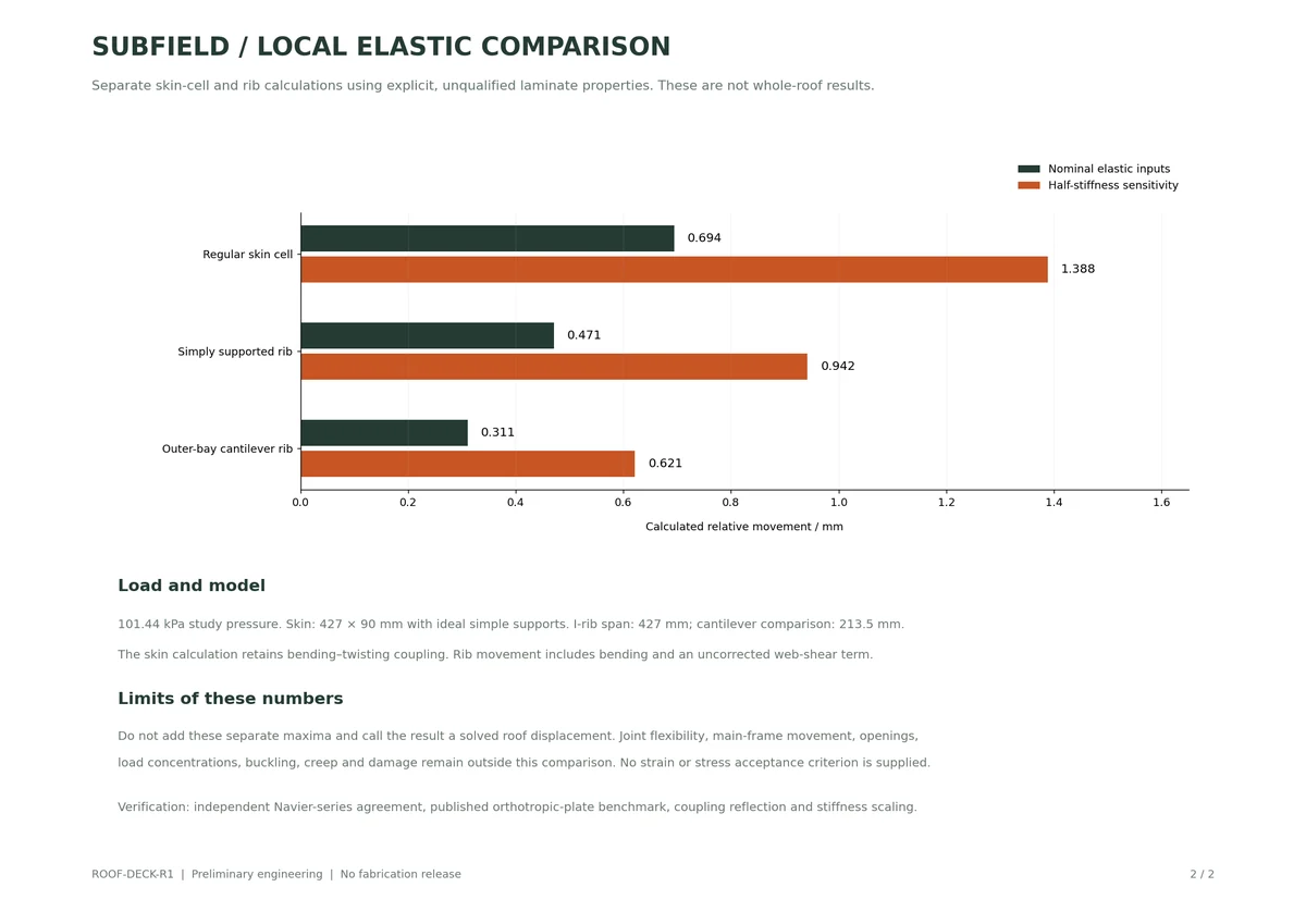
Under the retained 101.44 kPa study pressure, the ideal simply supported 427 × 90 mm skin cell gives 0.694 mm sampled maximum movement using the previous unqualified 3 mm shear-biased laminate. A regular 427 mm I rib gives 0.471 mm relative bending-plus-shear movement; the 213.5 mm outer-bay cantilever comparison gives 0.311 mm. Halving the assumed stiffness doubles those movements.
These are separate local calculations. They cannot be summed and presented as a solved whole-roof displacement. The plate model retains all D terms including bending–twisting coupling. The rib uses axial-biased caps, a shear-biased web and G times one web area; fillets, end plates and effective skin flange width receive no EI credit. No strength, buckling, creep or environmental acceptance follows from these numbers. The very large unsupported-flat-skin result in the JSON exceeds the small-deflection model's valid range and is only a diagnostic comparison.
The numerical method was checked against the documented orthotropic plate benchmark and Navier solution. NASA RP-1351 supplies the laminate-theory conventions. See local-deck-elastic-screen.json for inputs, convergence checks and exclusions.
- vessel-with-ribbed-deck.step — complete current geometric assembly. - ribbed-roof-assembly.step — existing roof members and the new deck/support parts. - roof-deck-skin.step — nominal skin with both access openings. - rib-section-100mm-reference.step — local I-section extruded 100 mm along its local Z for inspection; it is not an installed rib length or orientation. - print/ — full-size 30 × 60 × 100 mm profile sample in 3MF/STL, with mesh-closure and millimetre-scale checks. This is a nonstructural geometry sample; actual printer setup and calibration are unverified. - RIBBED-ROOF-DECK.blend / .glb and views/ — assembled and deck-lifted review views from the CAD meshes. The exploded pose is an inspection state, not a qualified lifting operation. - roof-deck-reference-review.pdf — nominal interface layout and local elastic comparison. - roof-deck-record.json and added-part-mass-takeoff.csv — geometry verification and assumed takeoff. - pumpout-corridor-check.json — independent STEP verification of the Ø350 vertical corridor from Z = 4 to 6482 mm, including the current lower frame. - current-cad-source.zip — complete current executable source, parameters, tests and pinned dependencies. - review-tools/ — the reference drawing script, requiring NumPy and Matplotlib.
The generator passed 2448 geometry/contact/service/STEP checks, with no reported interferences. The full CAD test suite passed 82 tests in 24.95 seconds. An independent STEP check confirmed the unobstructed vertical pumpout corridor; actual hose motion and retained-solids coverage remain unverified. Blender completed both review views and the images were inspected. Source and render hashes are verified before packaging. Geometry checks and elastic benchmarks are not physical product qualification.
The deck-to-body perimeter currently has no designed sealed and restrained joint. Complete its structural rim, bearing/hold-down system, gasket, access curbs, covers and risers. Resolve fabrication method, actual laminate/adhesive/barrier specifications, end-joint shear/peel, local instability, bending/torsion and whole-roof load sharing including the new pumpout structure. Define production tolerances, ply transitions, cure, surface preparation, inspection and handling. Complete tank penetrations, process equipment and all other outstanding system components before a complete manufacturing package can be claimed.
Extract current-cad-source.zip and run from its cad folder:
Source and revision record
Source: roof-deck-r1/READ-ME.md
Source SHA-256: e67a548fdd56fa148aca414dddf7a54c5d990d5e997629ee13de9bd372ede0d9
Geometry and images describe this development revision. Current product ratings and manufacturing release require separate qualification.
Return to the current product.
Explore the retrofit-only platform and its compatibility, installation and service objectives.
Explore the retrofit