Engineering records / Engineering record / CORE-FACEPLATE-SUPPORT-STUDY
Core Faceplate Support Study.
Geometry, analysis and remaining engineering work for Core Faceplate Support Study.
Retained development study. Dimensions, names and checks belong to this revision—not automatically to the retrofit-only product. Manufactured tank shells are deferred. No installation instruction, certification or manufacturing release is represented.
The source reasoning
Why this detail was investigated.
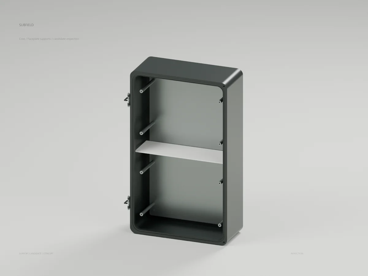
Internal inspection render · 62-part assembly STEP · Geometry checks
Read the research and limitsResearch record
The detail behind
the study.
Source-linked work for this revision. Reported checks describe the stated model or test; physical qualification and applicability to the current retrofit remain separate.
Internal inspection render · 62-part assembly STEP · Geometry checks
Eight keyed support posts now connect the two faceplates to the removable mounting tray. Each post has a lower assembly screw and an upper faceplate screw. The lower screws are installed from behind the tray before the tray enters the housing. One-millimetre hex keys locate the posts in shallow tray pockets; their torsional capacity is not qualified.
The upper supports are at X ±145 and Y 65/220 mm; lower supports are at X ±145 and Y −80/−235 mm. Bodies are nominally Ø12, extending from tray Z19 to the faceplate undersides at Z134 or Z133. The M4 screw/thread shapes are simplified development envelopes. Materials, machining details, tolerances, preload, thread capacity, support stiffness and vibration performance remain open.
All modeled new-part interference checks pass. The divider can rotate 20° and withdraw after the faceplates are removed. Its rotation was checked with conservative inflated envelopes covering every interval, followed by its continuous straight withdrawal envelope. With the divider and tray screws removed, the tray, posts and lower screws can withdraw together through the fixed enclosure. A nominal Ø10 driver barrel also clears the supports at each tray screw station. These checks omit actual electronics, wiring, hands and a qualified assembly/service procedure.
The STEP reimport contains 62 valid separate solids and passes the volume comparison. The inspection image hides the removed cover assembly and faceplates; its 43 visible CAD meshes were checked after reopening the Blender file. The image was visually reviewed.
This is a candidate geometry study, not a manufacturing release or a replacement for the completed Core R2 package. It has not yet been incorporated into the formal repository test suite. The earlier 38-part tray revision passed its separate 322-test full suite; that result does not cover this 62-part candidate. Divider attachment, rear-carrier retention, actual electrical packaging and physical qualification remain unfinished.
Source and revision record
Source: core-faceplate-support-study/READ-ME.md
Source SHA-256: 64fce30438a055d18c393a7a0bef1b3ea230df4940e22d5459e9c13ed25213ef
Geometry and images describe this development revision. Current product ratings and manufacturing release require separate qualification.
Keep exploring the research.
Engineering records / Engineering record
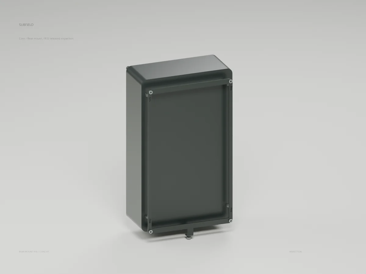
Core Lock Clearance R10
Geometry, analysis and remaining engineering work for Core Lock Clearance R10.
Engineering records / Engineering record
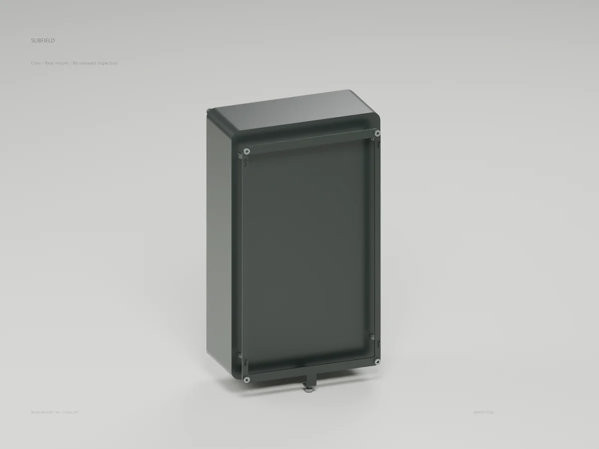
Core Carrier Formed R9
Geometry, analysis and remaining engineering work for Core Carrier Formed R9.
Engineering records / Engineering record
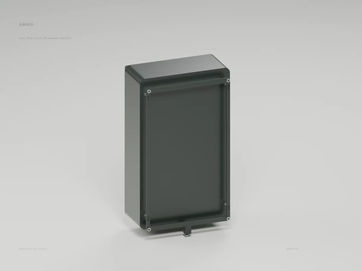
Core Rear Mount R8
Geometry, analysis and remaining engineering work for Core Rear Mount R8.
Return to the current product.
Explore the retrofit-only platform and its compatibility, installation and service objectives.
Explore the retrofit